
World and Eye Coordinate Systems
Generating a 3D View
Geometry is defined in the world coordinate system, a system whose origin and axis directions are meaningful to the creator of the geometry. The coordinate units are application-specific. They may be centimeters in mechanical design applications; meters in GIS applications; parsecs in astronomical applications; etc.
In order to generate a specific view of a geometric model created in this way, the graphics system must be told the world coordinate position of the viewer and the direction (with respect to world coordinates) in which the viewer is looking. This information defines a basic line of sight, but there remains a rotational degree of freedom: we don't know "which way is up". For example, the basic line of sight does not change if our viewer suddenly decides to stand on his/her head. Most graphics systems fix this degree of freedom by specifying an "up direction": a vector (also specified in world coordinates) that will be pointing vertically on the screen when the image is generated. (More precisely, the component of this vector perpendicular to the basic line of sight will be pointing vertically on the screen.)
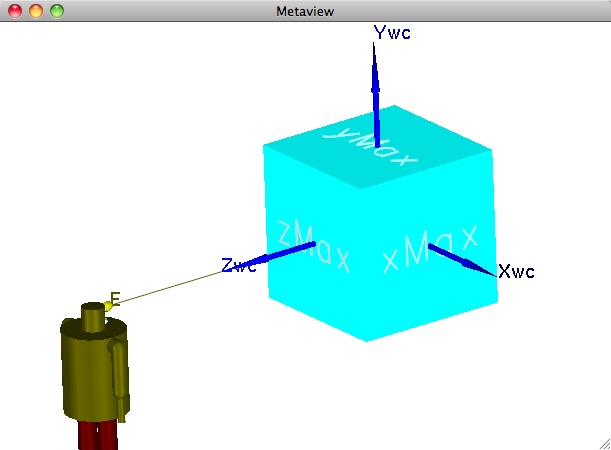
In the simple example shown above, we have defined a cube centered on the world coordinate system origin. We wish to view the front (i.e., the "zMax" face), so we position the viewer (or "observer", depicted here as a Robot) at the point marked "E" (for "eye"), fix the line of sight in the direction of the negative z- axis (the thin black line leaving E), and choose the world coordinate vector (0,1,0) as our "up" direction.
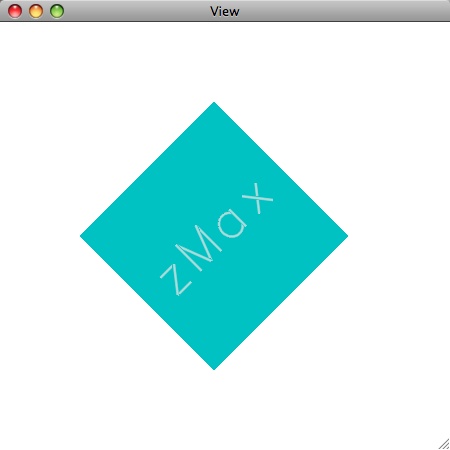
The image below shows what appears on the screen as a result.

Notice the title of the two images on this page. The "View" window shows the image of our model as it actually appears on the screen. In terms of what we see in the "Metaview" window, the "View" image is what our Robot viewer would see if he were standing at the point marked "E" in the "Metaview" window and looking in the direction suggested by the thin black line leaving "E". Therefore the scene in the Metaview window itself could be imagined as yet another external observer (for example, you!) looking at someone looking at our cube. It is thus a "view of a view", hence a metaview.
The final image on this page illustrates the same geometry and view, except with an up vector of (1,1,0).