

Stereo Frustums
Stereo Perspective View Frustums
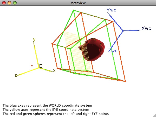
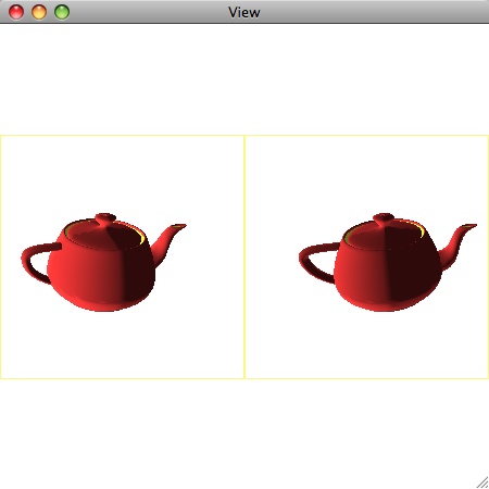
It is common to represent the left and right eye in the eye coordinate system as (-d/2,0,0) and (d/2,0,0), respectively, where d is the interpupilary distance. If we let these two eye points share a common viewport on a common projection plane, then we obtain the two perspective view frustums shown. The left eye and its view frustum are shown in red; the right eye and view frustum are shown in green. The stereo images generated using these assumptions are shown below.
EXERCISE
|
Run the program and experiment with additional view-related aspects of the simulation. (Don't fret over our poor robot observer who has been somewhat wildly stretched out so that his eyes match the current stereo separation. Remember you can always disable the display of the observer – as you can with many other metaview components – in the "Metaview" tab.) Try the following:
- Drag either the left (red) or right (green) eye point along the x-axis of the eye coordinate system. (They are restricted to the axis to avoid vertical parallax.)
- You can still drag the central reference eye point, E. Doing so when stereo is enabled moves the entire coordinate system (and the two eyes) as expected.
- You can also dynamically adjust the view frustum, either by clicking and dragging on it as before, or by adjusting the spinners (labeled VVxmin, VVxmax, VVymin, VVymax, near, and far) in the control panel.
- You can also use the "Stereo Sep" spinner in the control panel to adjust the separation of the eyes.
- The "Stereo" check box turns stereo on and off.
- If you change the projection type to Orthogonal, note that stereo is disabled. The reason is explained earlier in these notes. Do you remember why it is only enabled in perspective projections?
An alternative approach to the generation of stereo pairs abandons the notion of a common eye coordinate system (and hence common projection plane). Instead, each eye point could be used to define its own unique left- or right-eye coordinate system. The view plane normal of each resulting system could be computed using a common center of attention, resulting in two slightly different projection planes. As explained in [Slater, et al. and Hodges and McAllister], this approach is not commonly used because it leads to a non-flat virtual image plane that produces distortions in the image that can become a source of eye strain on the part of the viewer.