

World and Eye Coordinate Systems
The Eye Coordinate System
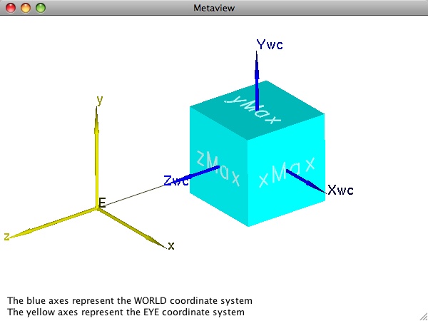
To facilitate graphics pipeline processing, most interactive graphics APIs employ a so-called "eye coordinate system" in which the eye is the origin, the x- axis is parallel to the horizontal direction on the screen, the y- axis (determined by the "up direction" as stated previously) is vertical on the screen, and the line of sight is the negative z-direction. (Negative so that the system is right-handed.) If all geometry is defined in this eye coordinate system, subsequent graphics operations like visible surface determination are simpler because they only require comparisons between z- coordinates. We see the eye coordinate system displayed in yellow in the first image on this page.
The first issue that arises is the mismatch between what the graphics programmer wants to use (world coordinates) and what the graphics system needs (eye coordinates). Fortunately, the graphics system can automatically transform world coordinates to eye coordinates based on simple information provided by the graphics programmer. Most commonly, the graphics programmer simply specifies two points (the position of the eye and the position of a "center of attention") and a vector (the "up direction" we have mentioned). These are all defined in world coordinates. The center of attention can be absolutely any point (other than the eye point) along the line of sight. One common strategy is to use a point which at least roughly corresponds to the centroid of the object geometry being viewed (hence the name "center of attention"). Doing so makes it much easier, for example, to generate successive views simulating walking around an object by simply changing the eye point.
Units in the eye coordinate system are the same as those in world coordinates. To map to the screen, the graphics system will eventually need to determine pixel locations corresponding to the coordinates. Moreover, it will also need to take into account a field of view to help determine what will actually be visible. An explicit model of the field of view is central to both of these needs. For perspective projections, we define a frustum, a truncated pyramid whose lateral sides delimit the field of view, and whose front and back faces define the so-called near- and far-clipping planes. Only portions of the geometry within the space delimited by all six sides will be visible. The image below illustrates a perspective viewing frustum for our simple cube example. The frustum is also drawn in yellow to emphasize the fact that its geometry is normally defined with respect to the eye coordinate system.
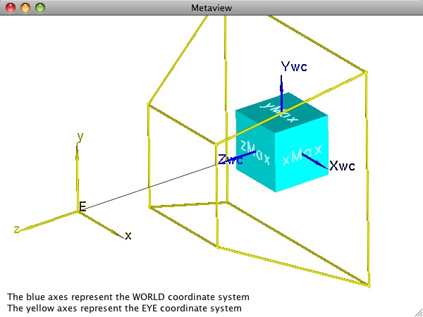
While the importance of the four lateral faces of the view frustum is no doubt clear in terms of defining the field of view, the need for and value of the near and (especially) the far planes may not be as obvious. We cannot see portions of the scene behind us, hence the field of view clearly cannot be allowed to include portions of the scene behind the eye. For reasons that become obvious when studying the mathematics of the projection operation itself, we must cut off the scene at some finite location in front of the eye. The near plane is used as this "cutoff" point. The exact location can be set by the programmer, however the best strategy often depends on how the graphics API bundles the overall viewing controls. In OpenGL, for example, the built-in functionality for defining the view frustum involves specifying an eye coordinate (xmin, xmax, ymin, ymax) that is defined on the near plane. As the figure indicates (and as you saw for yourself when experimenting with the metaview program in earlier exercises), moving the near plane closer to the eye while keeping its xy extent fixed causes the field of view to get very large very fast.
The far plane allows us to tell the system to clip away portions of the scene that are farther than that distance from the eye. Along with the near plane, one interactive view strategy that is helpful in certain applications involving very complex geometry is to slide the near and far planes in unison back and forth along the line of sight. This operation allows us to interactively "slice" through our model to reveal details that might not otherwise be visually apparent.
For applications that do not require this functionality (or for applications that simply do not desire far plane clipping), one might think that we should just eliminate the far plane along with its role in clipping. Indeed, some graphics APIs have various methods of doing this. The implementation of many interactive APIs like OpenGL, however, use hardware z-buffering for visible surface determination. These buffers are based on the ability to store depth values at each pixel in the display, and proper use of them requires some assurance that the depths of any two points that might project to the same pixel can be distinguished from one another. Since the graphics system cannot know what geometry (and in particular, what depth ranges) we will throw at it from frame to frame, it arranges internal transformations so that the majority of its depth resolution is reserved for the region of space between the near and far clipping planes. Knowing this, it is in our best interest to specify the near and far planes – especially if we have very complex models – so that they represent reasonably tight bounds on our model.