Linear Perspective

A Closer Look
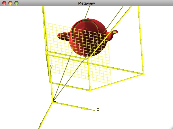
The first image on this page illustrates the basic idea behind the generation of a perspective projection of a 3D model. To determine what is visible at a given pixel on the screen, we trace a line of sight from the eye through the pixel. The first object encountered along the ray is what we see. A direct implementation of this idea leads to the basic ray tracing algorithm. While capable of producing stunningly realistic images, ray tracing is not a realtime operation with today's technology.
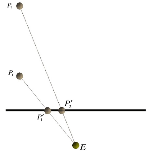
Most interactive graphics APIs like OpenGL define geometry vertex by vertex using piecewise linear primitives (lines, triangles, etc.). Each vertex is then mapped to the projection plane (and hence, the screen) by tracing lines of sight in reverse. The diagram below illustrates the basic idea. We focus on two points P1 and P2 (you can imagine them as being the two points on the teapot struck by the two rays above), and we study their projections. The diagram was generated by looking down the y axis of the eye coordinate system. The projection plane (and, in particular, the portion of it containing the viewport to be mapped to the screen) appears as a line segment. This image does not show the near and far clipping planes, nor any other part of the view frustum.

As the figure indicates, our two points P1 and P2 – even if they happen to have identical x and y coordinates – will project to two different points on the projection plane (P′1 and P′2). Note that the distance between P′1 and P′2 is not a simple function of the distance between P1 and P2, rather it is a somewhat more complex function of the relationship between P1 and P2 and E. For example, if we move E but leave P1 and P2 where they are, their projections (i.e., P′1 and P′2) change. One obvious implication is that our left eye sees P1 and P2 projected differently than our right eye does. Simulating that difference during rendering is the essence of generating stereo projections.

