
 |
NEW: Abstract
ModelView;
Modeling 101, Part 1: 2D; Shader program options
Abstract ModelView
There is only so much you can do in terms of handling a diversity of models when your only
tool is a single ModelView class. Constructor parameters – including
coordinate and other attribute arrays as we have seen in earlier examples –
buys some measure of
diversity, but eventually something more sophisticated is required.
This example illustrates one very common way to address this by
recasting ModelView as an abstract base class, thus enabling a
wider variety of types of models to be created and managed by the Controller.
So far, the Controller and the ModelView are only loosely coupled, the former needing
only three of the latter's methods:
- getMCBoundingBox (so the
Controllercan ask individualModelViewinstances for their bounding boxes, thus enabling theControllerto track the overall scene dimensions), - render (so the
Controllercan instructModelViewinstances to draw themselves), and - handleCommand (so the
Controllercan hand off keyboard events toModelViewinstances).
The basic idea is simple: redesign ModelView to be an abstract base class with
various public virtual (e.g., handleCommand and other event handling methods) and pure
virtual (in our case, just getMCBoundingBox and render) methods.
The Controller is unaffected by the fact that ModelView is abstract.
It still maintains a general collection of ModelView instances, but now the
actual instances can be very different concrete classes. For example, while our Controller
just sees multiple instances of ModelView, each might actually be a car, a house, a tree, a tower,
a mountain, a person, etc.
We gain one other important benefit from this restructuring.
In addition to factoring out common public ModelView interfaces, this
design also factors out into a new protected interface common pieces of the implementation
so that they need not be re-implemented in each concrete subclass.
Notice, for example, the two class
methods related to window-viewport computation. Window-viewport
manipulation is so common and so important that it is wasteful to require each subclass
to do it. The basic computations related
to window-viewport mapping (with or without aspect ratio preservation) are done in ModelView,
but only the float[4] of scale/translate factors is passed in and out. Since no
assumptions are made about how, if at all, this information is passed to GLSL shader programs,
the subclasses are free to use these common utilities
in whatever way works in the context of their shader
programs and other instance-specific computations.
Incidentally…
The concrete Controller subclass you are using can itself be subclassed.
Notice, for example, all of the original Controller methods
related to event handling
are virtual and can be overridden in subclasses you may wish to create.
As you create your own ModelView and Controller subclasses, do not forget the
two rules of thumb we identified earlier in the course.
Modeling 101, Part 1: 2D
This is the first of our examples in which real consideration must be given to how we generate the geometry necessary to realistically model something in our everyday experience. As we will see in class, this involves such matters as deciding on:
- units (centimeters, inches, feet, angstroms, etc.),
- where the origin of model coordinates should be,
- how the two or three axes are oriented with respect to our scene (usually only an issue in 3D), and
- how, if at all, we want to "parameterize" our model.
Parameters passed to constructors allow us to parameterize instances so that each – while structurally similar – can exhibit considerable variation in appearance. Parameterizing the classes in this way also allows us to easily construct text files that describe arbitrarily complex scenes composed of a variety of such instances. You will see a text input file used that way in this example.
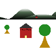
Our mountain village is constructed from three types of objects, each implemented as a
concrete subclass of ModelView: a house, a mountain, and a tree. The links below
show the way each was defined. These are the sketches
that I made while designing the objects to be used when creating various "mountain villages". Such hand-drawn sketches are a common and useful technique when modeling a scene. There
is also a link to an intermediate village printed on graph paper that I used to construct
alternative villages.
Drawings showing individual parametric designs and Overall scene design
- House(xb, yb, width, height, roofWidth, roofHeight)
- Tree(xb, yb, rTreeTop, rTrunk, height, numTreeTopPoints, numTrunkPoints)
- Mountain(xMin,
xMax, yMin, yMax, frequency, phase, numSamplePointsPerCurve)
A mountain is drawn as a triangle strip, alternating between vertices on y=yMin and vertices along a cosine curve defined by the various parameters. Specifically, frequency and phase are used as usual: cos(frequency*theta + phase). Theta varies from -π..+π, while the actual x coordinates vary from xMin to xMax. The -1..+1 value of the cosine function is then mapped to yMin..yMax using the linearMap function we saw when we first studied the window-viewport map in compute2DScaleTrans. You can see all this in Mountain::defineModel. - Partial mountain village
When studying the "render" method of the three classes, pay particular attention to:
- The new API pattern introduced: render does the usual preamble and cleanup processing, calling renderXxx in between. This pattern allows a ModelView instance to be rendered standalone in the usual fashion after being added to the Controller, or used as a component of some other instance, in which case it would not have been added to the Controller unless it was also meant to be drawn separately.
- The draw mode used on glDrawArrays calls. Be sure you understand why each mode is used and how it relates to assumptions about the order in which vertex data are placed in VBOs.
- Models are rendered by the Controller in the order in which they are added. You will note that two mountains are the first thing added to the scene when no input file is provided. (See makeDefaultScene in main.c++). Hence all other objects appear to be on top of or in front of the mountain. Similarly, houses and trees added after others appear to be in front of them. Until we get to 3D and automatic visible surface determination, this "order of rendering" will be the only way we can control visibility when two or more objects overlap.
Shader program options
Note that each concrete subclass in this example uses its own unique shader program. While this is one common approach, there are limitless shader program management options. The MandM example we will study next illustrates another very common shader program management scheme, namely the use of a subclass of ModelView that only handles 3D lighting and viewing, but is still abstract so that the lighting model can be easily shared among a wide variety of concrete subclasses (e.g., houses, cars, trees, buildings, etc.).
Running the Program
Just running this program without command line arguments as:
causes the makeDefaultScene function in mountainvillage.c++ to be called, and it creates a "village" with two houses and two trees in front of two mountains as shown on the left.
Alternatively, you can pass a text file in a very simple format that describes some other "mountain village". The image shown in the thumbnail at the top of this section, for example, was produced from the Village.txt file passed as:
 |
NEW: Modeling 101, Part 2: 3D; 3D viewing, & lighting using a common shader program
Creating and rendering 3D models requires not only the introduction of 3D coordinates and surface orientation specifications (i.e., normal vectors), but also a method for simulating a general 3D view of the scene. Viewing was of course also required in our 2D scenes, but the requirements were so basic – just the generation and use of our scaleTrans – as to be almost unnoticeable. For 3D scenes, a more comprehensive approach is needed. We will start with 3D modeling, then consider 3D viewing along with lighting and shading.
Modeling 101, Part 2: 3D
In addition to units and origin placement as mentioned in "Modeling 101, Part 1: 2D", it is now also important to choose an orientation for our model coordinate (MC) axes. Usually this is just a matter of deciding how we map, for example, height, width, and depth of our objects to MC x, y, and z axes. For example, if I am modeling a room, I may choose to have the length and width of the room lie along the MC x and y axes, respectively, and the height along z. This choice must be considered when specifying a view of the resulting 3D scene (i.e., when specifying the eye, center, and up parameters used to define the mapping from MC to EC).
Since normal vectors have the potential of being different at each vertex, we must treat them as per-vertex attributes. However for some surface types (e.g., the faces of the block, the M shapes, and the tetrahedra), the normal vector is constant over the primitive calls used to render them. Hence we do not use VBOs for normal vectors for those objects. Instead we will use glVertexAttrib* calls issued in the render method to specify the normal vectors immediately before rendering each face of those shapes.
Basic Modeling in 3D
Obviously all coordinate arrays passed to the GPU via glBufferData calls need to encode
3D (x, y, z) coordinates.
The Tetrahedron model uses the cryph utilities while doing so, in part because a
tetrahedron is defined via its four points, and we must be able to compute the normal vector to each
of its four faces. This is simplified using the cryph utilities as you can see in the
code.
By contrast, notice that Block,
Cylinder, and M simply create directly these
coordinates in arrays of float
without the use of the cryph utilities. This does not
suggest that that is "better" in any sense.
It is
easy since our instantiation of those shapes in this example
have simple relationships with respect to the x, y,
and z axes. However, reexamine the code and consider what would be required if,
for example, we wanted to add
a cylinder whose axis was parallel to the z axis. Or perhaps whose axis was, say, (-0.3, 0.472, 0.7).
Similarly, what if we wanted a block tilted up on a corner?
We could not use the same Cylinder or Block
code to do so. Instead, significant code modifications would be required. Had those
shapes been defined in general position and orientation using the cryph
utilities, however, it would have been trivial to make changes such as these.
Another example in which defining shapes directly using cryph points and vectors simplifies
geometry creation is the following. Suppose you want
to create a model of a bicycle and decide to use cylinders to represent the spokes.
You would not start from the Cylinder class here. Instead, you would most likely want to
develop an interface that creates a cylinder from two 3D points and a radius; e.g.:
Cylinder(cryph::AffPoint PBottom, cryph::AffPoint PTop, double radius).
Such an interface would work for cylinders in any position or orientation in space. We will
see such an interface for Cylinder (and other) shapes in our next and final example program.
glDrawElements
The Block example introduces the glDrawElements function. This function allows
you to tell OpenGL to randomly access vertices in a VBO rather than only use contiguous subsets
as glDrawArrays requires. Three faces of the cube are drawn using glDrawArrays;
the other three are drawn using glDrawElements.
Study the code and be sure you understand how all six faces
are drawn, why they are drawn that way, and how glDrawElements works.
ModelView subclasses with more sophisticated internal structure
- Using a Basketball goal as an example, here is a rough sketch of how more interesting ModelView subclasses can be created and used in our framework.
- An option would be to replace one or more of the individual VAO-VBO sets in the Basketball goal example with calls to the renderXxx method of some other class as suggested in bullet "A" under "Modeling 101, Part 1: 2D" above.
Macintosh OpenGL developers: Be sure to read the notes regarding glDrawElements in the Platform-Specific Notes page.
3D Viewing
Viewing requires:
- A basic line of sight so that we can determine how the surfaces in our model are oriented
with respect to our eyes.
⇒ 4x4 "mc_ec" Matrix (Computed on CPU; applied in vertex shader) - A scheme for projecting the oriented 3D surfaces onto a 2D plane that corresponds to our
display surface. (This step will incorporate the CPU side of the
MC⇒LDS transformation
performed by compute2DScaleTrans, but it will not use
compute2DScaleTrans.)
⇒ 4x4 "ec_lds" Matrix (Computed on CPU; applied in vertex shader; used instead of "scaleTrans") - An algorithm to simulate how light from sources defined in the environment
reflects off surfaces and appears to our eye.
⇒ Lighting and Shading Model (Implemented in the fragment shader) - A scheme for ensuring that surfaces that would be obscured by others from this line of
sight do not appear on the display.
⇒ VSD (Visible Surface Determination): Performed in non-programmable part of the GPU pipeline after the fragment shader executes
These topics will be covered in some depth and generality in lectures. Here we introduce the key ideas in the context of our "MandM" example. For each of the four requirements above, a high level idea of how they are satisfied follows. (The getMatrices method mentioned in items 1 and 2 derives its name from the fact that two 4x4 matrices are used to encode required information. These matrices are returned from the getMatrices method.)
- ModelView::getMatrices will use the model coordinate (MC) descriptions of (i) the position of the viewer (the "eye point"), (ii) the position of the center of attention in the scene, and (iii) an orientation vector (the so-called "up" vector). The MC specifications of the two points define the line of sight. The MC "up" vector fixes the rotational degree of freedom about the line of sight. That is, it establishes how the direction from the viewer's feet to the viewer's head relates to the MC axes. The line of sight and orientation are encoded in the first 4x4 matrix generated by and returned from ModelView::getMatrices. We will refer to this matrix as mc_ec since it maps coordinates from MC to eye coordinates (EC).
- The second 4x4 matrix generated by and returned from ModelView::getMatrices encodes how 3D geometry is projected onto a 2D plane. A projection type (e.g., orthogonal or perspective) along with a 3D bounding box defined in eye coordinates (EC) will be used to generate the transformation matrix. Recall that this matrix will include the (sx, tx, sy, ty) that we used for 2D scenes. We will refer to this matrix as ec_lds since it maps coordinates from EC to logical device space (LDS).
- Simulating how light reflects from surfaces requires, among other things, that we directly define
the outward pointing vector that is perpendicular to a point on a surface being rendered. This
is necessary because the intensity of light reflected from a given point on the surface decreases
as the angle of incidence away from this normal increases.
This is the requirement on which we must focus most strongly right now.
If I am rendering a cube, all points on a given face of the cube have the same outward pointing vector; however if I am rendering a sphere, the normal vector is different at every point on the surface. Other common surfaces are somewhere "in between"; for example, all points along a cylinder ruling (a straight line parallel to the cylinder axis) have the same normal vector, but as we move around the circumference of the cylinder, each point has a different normal. Careful simulation of these effects is what makes scenes like the one posted here appear three-dimensional.
- OpenGL uses a very simple scheme based on a so-called "depth buffer" to determine visibility of surfaces.
Framework Considerations
When constructing 3D scenes consisting of real-world objects, we usually want all to be rendered using the same viewing specification. Notice that the abstract class ModelView factors out the common code related to simulating the viewing environment. This code is implemented using static (i.e., class) methods using static data so that it will be common across all instances of all concrete subclasses.
As mentioned above, viewing specifications are encoded into 4x4 matrices which are then sent to variables of type mat4 in your GLSL program. Those variables are typically uniform, and you will see in this example a new variation of glUniform, namely glUniformMatrixsizefv. The size can be 2, 3, or 4 (indicating a 2x2, 3x3, or 4x4 matrix, respectively), or ncolsxnrows (e.g., 2x4). Read the API spec for further details, especially for the ncolsxnrows version. We will only use mat3 and mat4 in this course.
Matrices in a GLSL program are assumed to be stored in column-major order. Note that the general form of the glUniformMatrix call that we will use is:
The first two parameters are the same as for the glUniformntv function we have seen. (It is possible to declare arrays of matsize instances in your GLSL program.) The transpose parameter should be true if the data in the matrixArray are in row-major order (and hence must be transposed on their way to your GLSL program). It should be false otherwise.
So how should ModelView::getMatrices create the matrices? While we will cover the major ideas in depth in class, here are a few "previews of coming attractions".
Recall that ModelView instances must report the region of model coordinate space they occupy, and the Controller keeps an accumulated MC bounding box. We can easily use that information to compute appropriate MC specifications for eye, center, and up. There are actually a couple standard approaches depending in part on the types of interactive view manipulations you wish to support. For example, the midpoint of the overall accumulated bounding box could be used as the center of attention, then we could just move out away from that point in some direction to establish an eye point.
How about the projection parameters? Recall that they must be defined in EC space. While the bounding box we have is in MC, we can create reasonable projection parameters by remembering that the units (meters, feet, inches, etc.) of MC and EC are the same. This means we can consider a sphere that circumscribes the bounding box, and derive projection parameters based on the radius of this sphere.
3D Lighting
The data and computations required to implement a lighting model are sufficiently common that it makes sense to encode them once in a GLSL shader program that can be shared by all concrete ModelView subclasses. Notice that Block, Cylinder, M, and Tetrahedron all use the same shader program. The vertex shader code provided in this example program packages relevant per-vertex attributes and passes them off to the fragment shader where the Phong local lighting model will be implemented. The existing fragment shader is basically a placeholder for this lighting model. You will be elaborating this model in stages as we move from projects 2 to 3 to 4. Successive elaborations from project to project wil include:
- more sophisticated models for light-surface interaction.
- use of one or more light sources, each of which may be a different type (e.g., directional, positional, spot, flood, etc.).
- defining the actual direction or position of a light source in either MC or EC (or even others).
- modeling the strength and color of light sources.
- simulating complex texture (brick, wood, etc.) on surfaces.
3D Viewing and Lighting: A Look Ahead
As you can see, there are several details involved in managing models, viewing, and lighting in 3D. In our next and final sample program, we will introduce SceneElement, a subclass of ModelView that is also abstract and which factors out these details in a way that facilitates the process while not sacrificing the ability to create a rich variety of 3D models. Also introduced there will be struct PhongMaterial which facilitates the CPU side of managing material properties used in the Phong local lighting model we will be studying.
Friendly Reminder
As you start exploring some of these advanced lighting model features, you will find yourself wanting to declare arrays of uniform variables related to light sources. You should re-read the glUniform syntax notes before doing so!
Some project 2 links:
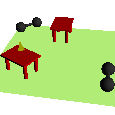 |
NEW: struct PhongMaterial & class SceneElement to facilitate CPU side of common lighting model; class BasicShape & class BasicShapeRenderer for creating & rendering common shapes like spheres, cylinders, cones, and blocks
As you develop more sophisticated lighting models, you will recognize the value of factoring out common CPU-side aspects of implementing such a model. We will see sets of material properties, light source specifications, and other considerations that all concrete ModelView classes will be required to manage. Hence, one of the first things you will notice in this example is the introduction of a new (and still abstract) subclass of ModelView called "SceneElement". This new class will be used to factor out all the common aspects of a lighting model while still being independent of the type of model, thus preserving the advantages that we realized when first introducing the abstract base class ModelView. Actual elements of the scene (in this case, Barbell, Table, etc.) will then be defined as subclasses of SceneElement.
Two Method Naming Conventions
Following up on this idea of increasingly sophisticated models and the need to modularize implementations to keep code manageable, you will notice a naming convention with respect to various aspects of specifying model and attribute data. We use methods beginning with "define" for initialization of data, typically called only once from a constructor. We then use methods beginning with "establish" to set values during display callbacks (i.e., when your render methods are called). This convention is used primarily in the context of establishing the viewing environment (establishView), the lighting model parameters (establishLightingEnvironment), material property parameters (establishMaterial), and (later) texture mapping (establishTexture). You will see prototypes for these in SceneElement.h above.
struct PhongMaterial
This struct contains definitions for all the Phong lighting model parameters. The SceneElement class stores an instance of PhongMaterial, the intent of which is to facilitate a common way for all concrete subclasses to send these values to the shader program during a call to render. Specifically, subclasses call SceneElement::establishMaterial which is expected to issue appropriate glUniform calls to send values to the shader.
class SceneElement
This abstract class is a subclass of ModelView that supports the CPU side data and methods needed to support a lighting model. Much of this class is a placeholder here. You will flesh out the specifics as we cover them in class. Note in particular the instance methods whose name begins with "establish". These methods are intended to be called from render methods in your subclasses as can be seen in the example code here.
class BasicShape
The BasicShape class is intended to provide an easy-to-use interface for creating common shapes. Internally the outer surfaces of all "basic shapes" are represented as piecewise triangles. Basic shapes such as spheres and cylinders are approximated to a user-specified level of accuracy.
The BasicShape class includes two sets of public interfaces. The first is comprised of a set of public factory methods (i.e., class methods that create instances of BasicShape), all of whose names begin with "make". See makeBlock, makeSphere, etc. These are the only methods that should be called from your scene creation code. In particular, note that there are no public constructors for class BasicShape.
The BasicShape factory methods create a collection of VBOs (vertex lists, index lists, normal lists, etc.) along with information that can be queried that describe how the shapes should be rendered. To facilitate correct processing of all the supported data representations, there is a BasicShapeRenderer class (described next) which should be used by all clients. The second set of public interfaces to class BasicShape is intended to be used only by a BasicShapeRenderer. Specifically, public instance methods of class BasicShape should only be called from instances of class BasicShapeRenderer.
Texture coordinates can optionally be generated for BasicShape instances as described in the documentation cited above. For BasicShape instances created using the makeBlock routine, refer also to the additional documentation for texture mapping on blocks.
class BasicShapeRenderer
The BasicShapeRenderer class is intended to be used as an easy way to render shapes created by the BasicShape::make* factory methods. Note that class BasicShapeRenderer is not a subclass of ModelView. This is in large part because we do not want to make anything about the BasicShape functionality depend in any way on a specific lighting model or shader implementation. All the BasicShapeRenderer interface requires is generic support for (i) 3D vertices, (ii) 3D normal vectors, and (iii) 2D texture coordinates. By default, it assumes our convention that the shader program variable names for these quantities are mcPosition, mcNormal, and texCoords. If you use BasicShape and BasicShapeRenderer with a shader program that uses different names, the BasicShapeRenderer::setGLSLVariableNames method can be used to tell BasicShapeRenderer instances to use those other names.