
 |
NEW: Coordinate Systems; Attributes and Attribute Location Lookup
Coordinate Systems
In our "Hello, OpenGL" example, the geometry of the triangle was specified in class ModelView itself. It is much more common and realistic for model classes like that to take constructor parameters that specify the geometry and other attributes. Among other things, this allows multiple instances to be created and rendered.
That is what we see in this example. Note that class ModelView takes an array of (x, y) coordinates to define the geometry of a triangle. We then create two such triangles. But the problem this introduces is that we cannot assume the coordinates will be in our LDS -1 to +1 range. Instead, we assume they are defined in so-called "model coordinates" (commonly abbreviated as "mc"). This leads us into the wonderful world of coordinate systems used in APIs like OpenGL.
OpenGL uses a variety of coordinate systems in different contexts. We will study them as we progress through the course, but three must be understood now: Model Coordinates, Logical Device Space, and Pixel (also sometimes called Screen or Window) coordinates.
-
Model Coordinates (MC): This is the coordinate system (and the units)
in which you define the geometry of your model. The coordinate data sent
to the GPU in VBOs are usually expected to be provided in MC. (See
ModelView::initModelGeometry in this current example.) You are free to assume
whatever units make sense to you in the context of your application. You may want to
work in centimeters,
angstroms, kilometers, etc. All coordinates are measured with respect to an assumed origin and
axis assignment, also of your choosing.
As an example, suppose you are creating a model of a house. You may choose to assume that (i) the origin is at the lower left corner of the garage door, (ii) the x-axis points along the ground towards the lower right corner of the garage door, and (iii) the y-axis points up the garage door. Or you may choose any other assignment that makes sense to you.
- Logical Device Space (LDS):
In the preliminary stages of the graphics pipeline, OpenGL
assumes the window on our screen is addressed as: -1≤x≤+1 and
-1≤y≤+1, regardless of its actual shape or size on the display.
Our "Hello OpenGL" example produced a triangle on the display because its coordinates
were all in this range. Look again at the coordinates that were specified in
ModelView::initModelGeometry
of that example. In essence, we created a model
in which MC and LDS were identical. This is not common – in fact, it is highly
unusual – hence this issue is front and center in the current example.
The vertex shader is typically assigned the task of mapping the coordinates it's given into LDS space. The vertex shader in "Hello OpenGL" was able to simply pass the incoming vertex coordinates along unmodified since they were already in this range. (Review hello.vsh in the "Hello OpenGL" example.)
As can be seen in the example here (specifically in the coordinate array initializations in the main program in twoTriangles.c++), the MC system being used cannot possibly be used as LDS – our triangles not only occupy a region considerably larger than the 2x2 LDS range, but they are also far from the origin. They will need to be scaled and translated into LDS space. Consider the following high-level overview of the situation depicted in this example along with the relationships among the coordinate systems:
Model Coordinates (MC) ⇒ Logical Device Space (LDS) ⇒ Pixel coordinates on screen. Definitions Controller instance variable overallMCBoundingBox:
This is the smallest bounding box in Model Coordinates that encloses the entire scene. It is maintained on a per-Controller instance basis since each Controller can manage a different set of ModelView instances.ModelView class variable mcRegionOfInterest:
This holds the portion of Model Coordinate space we currently wish to see on the screen. In our framework, it is initialized to the Controller's overallMCBoundingBox, but it can grow larger, smaller, and/or move around at any time. It is maintained on a per-ModelView class basis since all ModelView instances associated with the same Controller must use the same mcRegionOfInterest.The discussion that follows expands upon the definitions presented in the sidebar table on the right.
In our architecture, the
ModelViewclass is responsible for computing the sx, tx, sy, and ty shown in this high-level overview. But in order to do so, it must be told how much of MC space should be mapped to LDS. (We will refer to this as the "MC region of interest".) While the ModelView instance knows its own extent (see ModelView::getMCBoundingBox), there will generally be many other ModelView instances about which it knows nothing. Moreover, a user may be zooming and panning around the scene, hence the current "region of interest" in MC space may be continually changing, unbeknownst to any one ModelView instance.The ModelView class is told what to use as a region of interest when someone calls the public class method ModelView::setMCRegionOfInterest. During subsequent display refreshes, the ModelView::compute2DScaleTrans method will create the sx, tx, sy, and ty necessary to map the current MC region of interest to the -1..+1 range of LDS.
In all of our sample programs, the main program (or a function called directly from the main program) initializes this region of interest so as to enclose all ModelView instances created and added to the Controller. The main program code queries the Controller for its overall MC bounding box – the region containing all ModelView instances – and then uses this overall bounding box to set the region of interest. Examine the code in the main program of twoTriangles.c++, and trace through the Controller code that executes when the two addModel calls are executed.
In order for this process to work reliably, each
ModelViewinstance must implement ModelView::getMCBoundingBox so as to return the MC x, y and z limits of a box that "tightly" encloses the geometry of the instance. When the instance is added to theController(see Controller::addModel), the Controller asks the ModelView for this bounding box, and then the Controller updates its monotonically increasing "overall bounding box" – the region of MC space that "tightly" encloses all models added to the Controller.Trace what happens when the render method of
ModelViewis called. After establishing its GLSL program, ModelView::render calls the class method ModelView::compute2DScaleTrans. The sx, tx, sy, and ty values are computed using the "region of interest" and are returned in the scaleTrans array. Those values are then sent to the vertex shader in uniform vec4 scaleTrans. (See twoTriangles_V1.vsh.) - Pixel (or screen or window) coordinates: These coordinates are actual pixel offsets from the lower left corner of the current window created for your program. LDS coordinates are "logical device coordinates" – they indicate relative position inside the window. By contrast, pixel coordinates are actual pixel offsets on the screen. So as the window is resized, for example, the LDS coordinates of our triangle vertices will not change, but their pixel coordinates will change. The OpenGL pipeline maps from LDS to pixel coordinates at a pipeline stage somewhere between the vertex and fragment shader.
In GLSL code, we will typically prefix variables used to hold coordinate data with "mc" or "lds" to emphasize the coordinate system in which the data is defined. Since coordinate data initially passed to the vertex shader are typically given in model coordinates, variable names for these inputs are typically prefixed with "mc" as well.
As a final note, observe that
the ModelView only knows about MC and LDS; the Controller only
knows about LDS and pixels. (While the Controller "blindly" accumulates
an overall MC bounding box as described above,
that does not suggest that it "understands" or uses models
coordinates in any way.) Hence LDS will be the coordinate system used whenever
communication of general coordinate data between the ModelView and the
Controller is required. We will see one example of this in the context of
handling interactive events in the "Simple Events" section below.
These coordinate system issues and how they relate to our framework and programming conventions are absolutely critical to understand. Therefore, before moving on to attributes, let's take one more look at how our framework and related conventions built into our main programs like twoTriangles.c++ use this "round-trip excursion" from MC to LDS to pixels and back:
Attributes and Attribute Location Lookup
In our "Hello OpenGL" example, the CPU-side program assumed that the mcPosition variable was at location 0 in the GLSL program, and the fragment shader arbitrarily assigned a color of dark yellow when it was called. Neither convention is very general. For an alternative to the former issue, we will see how to look up attribute variable locations once the GLSL program has been compiled and linked. We will use two ShaderIF methods (pvaLoc and ppuLoc) to perform this lookup. The locations returned from these methods will be passed to routines such as those we have already seen. For example, instead of writing: "glEnableVertexAttribArray(0);" as we saw in "Hello, OpenGL", we will write "glEnableVertexAttribArray(shaderIF->pvaLoc("mcPosition"));".
As for a more general way to communicate color and other attributes, there are two ways for a client application to communicate information to shaders to allow them to operate in more general ways. The first is demonstrated in this example, and it employs what we call "per-primitive" attributes whose values are specified using uniform variables. The values of such variables are allowed to change only between successive primitive display function calls, hence the name "per-primitive". A typical primitive display function is glDrawArrays. In this example, we pass explicit colors as uniform variables. (The next example continues to employ uniform variables, but in a more general way that begins to provide some insight into the power of shader programming.)
The second application-level way to specify color and other attributes uses "per-vertex" attributes. We have already seen an example of this: passing the coordinate data itself (i.e., in "mcPosition"). However we will revisit per-vertex attributes and begin to explore the many additional possibilities that they provide in item #4 below.
 |
NEW: Basic event handling; More Elaborate Fragment Shader Coloring
Basic Event Handling
This example introduces event handling. Specifically, we focus on keyboard events which occur whenever the graphics window has input focus and the user presses a keyboard key. Like all events supported by GLFW, there is a two-part process involved in event handling: registration of an event callback handler, and the implementation of that callback.
Part 1: Callback Registration and UseThe GLFW window manager – like many of its ilk – employs a scheme whereby clients register callback functions to be invoked whenever the window manager detects some sort of relevant event. Study GLFWController::initializeCallbacksForRC. This method is called from the GLFWController constructor. The glfwSetXxx methods instruct GLFW to call the specified GLFWController class method whenever an event of the type encoded in "Xxx" is detected. For example, observe how an event passed to the GLFW::charCB class method is passed to the Controller::handleAsciiChar instance method which then, after some preprocessing discussed below, passes the relevant data on to each of its registered ModelView instances.
Part 2: Event Handling
Once any type of event has been received, the Controller
is responsible for making sure that any and
all "interested parties" have access to the event details. There are many ways of doing this;
typically the best approach depends on the type of event.
Here we are focusing on keyboard events for which the Controller
immediately sends all the relevant event information to all ModelView instances
it is managing, each of which may choose to process or ignore the event.
ModelView instances often need to know the current position of the mouse in addition to the other event data (e.g., the keyboard key that was detected). The GLFWController::mouseMotionCB tracks the current mouse position independent of all other events (clicks, keys, etc.). When an event occurs for which this position is desired, the last mouse position is passed to the Controller method along with the other event data. The Controller translates these pixel coordinates to LDS space as we saw in "Step 5" of MC↔LDS↔Pixels. It then passes the event data along with the LDS mouse coordinates to the ModelView instances it manages by invoking the ModelView::handleCommand method. (See Controller::handleAsciiChar and its call to pixelPointToLDSPoint for details.)
Some events are intended to be handled by all ModelView instances. Others should be processed by exactly one. To support these two modes, the ModelView::handleCommand method returns a bool. If this returned value is true, the Controller will continue to send the event to other instances; if it is false, the Controller will stop sending the event out.
In twoTriangles_V2, ModelView instances handle the event as follows. If the cursor position
is inside the bounding box of the triangle, it interprets keys '0', '1', …, '9' as specifying
which color mode the fragment shader is to use for that particular triangle. It then returns
false to the Controller, telling it to stop sending the event.
Otherwise it assumes the event is not intended for it and simply returns true, signaling to the Controller that it should continue sending the event to
other instances.
More Elaborate Fragment Shader Coloring
Rather than pass an explicit color to the shader program, this example passes the current value of the per-primitive integer attribute mentioned in the last paragraph to the fragment shader. The attribute is used to select one of a variety of schemes to compute a color. For some of the algorithms, the LDS coordinates of the fragment are used to compute colors in very general ways. To enable this, we see a small, but important, change in the vertex shader: it passes the computed LDS coordinates into the fragment shader using "out" variables which are then imported into the fragment shader as "in" variables. That is, the same values used to set the x and y components of gl_Position are also separately output as "out" variables. This then enables the different colorMode settings to employ trigonometric and various other functions using the LDS coordinates we send to the fragment shader.
Summary of Some Useful GLSL Built-In Functions
- sin, cos, pow, sqrt, and most of the other typical math functions. Note that these take/return simple floating point values as well as vec2, vec3, vec4, mat3, mat4, etc.
- radians: converts a given angle or angles in degrees to radians.
- degrees: converts a given angle or angles in radians to degrees.
- Functions often used with colors (although applicable to any type): clamp(value, minValue, maxValue), mix(val1, val2, fraction).
For a complete list of the built-in functions, see chapter 8 of The OpenGL Shading Language document for the version of GLSL you are using. Links to these documents can be found at the top of the GLSL Overview web page.
Notes on the syntax of glUniform calls
Like several other API entry points, there are many syntactical variations of the OpenGL function glUniform. They are used to copy updated values from your CPU code to the storage allocated on the GPU for the corresponding uniform variable. Be sure to study the API summary for glUniform! Briefly, the non-matrix variations fall into two categories:
- glUniformnt(ppuLoc, val0, … valn-1)
where n is 1, 2, 3, or 4, and t is either f, i, or ui for single precision float, int, and unsigned int, respectively. When n is 1, the routine sets the single float, int, or unsigned int using the provided parameter. Otherwise the target of the assignment is expected to be a vecn, ivecn, or uvecn, respectively. - glUniformntv(ppuLoc, count, valArray)
where n and t are as above, and v means the data is being passed in an array instead of in individual parameters. When using this form, be sure to note the distinction between the n in the name and the count parameter. The former (along with t) identifies the base type of the uniform variable in your GLSL code as noted in #1 above; the latter indicates how many elements of that type you are sending in this call. If the target is not an array in your GLSL program, count must always be 1. If you are sending data to a uniform array, then count can be no more than the minimum of (i) the number of n-tuples in the valArray parameter and (ii) the declared size of the uniform array in the GLSL program.
| Starring... |
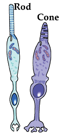 |
- Understanding color begins with an understanding of the human physiology of color perception, including the roles played by the rods and cones in the human eye. See any standard graphics reference text for details.
- JOGL:
Run this program to view, slice into, and generally query and interact with various "color spaces".This program is not currently available. Instead, you can view a few sample static color space images. - ColorBrewer for selecting color schemes in visualization contexts
- www.brucelindbloom.com (then click on "Math") ; www.easyrgb.com: These sites have a wealth of color-related information including algorithms for converting between a wide variety of color spaces.
- Looking for how to get the RGB values for your favorite color? Fuchsia? Maroon? Deep sky blue? Just google it! "rgb values for fuchsia"
- Most laptops/desktops have software utilities that allow you to hover the mouse over an area of the screen and read off the RGB value underneath the cursor.
 |
NEW: More general use of per-vertex attributes; Aspect Ratio Preservation
Per-Vertex Attributes
So far we have used per-vertex attributes as stored in VBOs and packed into VAOs strictly to communicate coordinate data to our GLSL vertex shader program. This example illustrates passing completely general per-vertex attribute data into the vertex shader. In addition to (and/or instead of) using these per-vertex values in the vertex shader, it can pass them along to subsequent shader stages (for now, just the fragment shader). When passing per-vertex data to the fragment shader, the values are linearly interpolated across the interior of the primitive. If the mode in the current glDrawArrays call is some GL_TRIANGLE_*, then each fragment (i.e., each pixel inside a triangle) will receive a value for the attribute computed as a weighted average of the three vertex attribute values of the containing triangle. The three weights are inversely proportional to the distance between the fragment and the three vertices. If the mode is some GL_LINE*, then the attribute is linearly interpolated along the length of each line segment drawn.
In the example here, vertexFraction and vertexColor are passed out of the vertex shader and into the fragment shader. Note how those interpolated values are then used in the fragment shader.
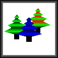
In addition to the three trees, note that there is a black "frame" around them defined as a single GL_TRIANGLE_STRIP with per-vertex colors causing it to be black on the outside, gradually brightening to a lighter gray as it approaches the interior.
Like the pair of "twoTriangle" examples we studied, we have designed the ModelView constructor so that all four objects can be created with a single ModelView class. Specifically, parallel arrays of coordinates, colors, and fractions are passed to the constructor. These will be sent to the GPU in parallel VBOs as you can see in ModelView::initModelGeometry. (The fractions are used as a measure of the distance along a primitive in some direction and are used for some of the color modes described next.)
The fragment shader uses a colorMode uniform variable as did the fragment shader in twoTriangles_V2, but this time it uses the mode to decide whether to color the trees based on their explicitly assigned per-vertex colors, by assigning a gray scale based on the fraction a pixel is across the primitive, by multiplying these two colors together, or by using an arbitrary fixed color (a darkish violet). Note also that "picking" the items in this scene is not performed based on the cursor location, rather based on the key pressed. That is, keys 0, 1, 2 select, respectively, the first, second, or third tree rendered; key 3 selects the surrounding frame. With each key press, the code cycles among the four color generation modes for the selected ModelView instance.
There is no argument that either method of selection is "better". The goal is simply to illustrate different possible schemes. You may well devise other schemes that work in scenes you create and manipulate.
An easy-to-overlook, but vitally important concept:
Study the code in ModelView::initModelGeometry to see how per-vertex colors and per-vertex fractions are assigned to the vertices of the geometry. This example differs from all the previous ones we have studied in that we create three VBOs, all of which are associated with a single VAO. Whenever multiple VBOs are associated with a single VAO, the buffers are "parallel buffers". That is, the ith element of each is associated with the ith vertex. It is the job of the Vertex Fetch stage of our pipeline to extract all the corresponding per-vertex values for each vertex shader execution, making sure that the appropriate "in" variables have been assigned these values. Observe that these three attributes are all simply declared as "in" variables of various types.
| Terminology |
| "Window" has come to mean two different things in interactive computer graphics. It refers to
the region on an interactive display created by a window manager that typically has a title bar, a close button, etc.
We shall refer to this as the "window manager window" (or "WM Window"). The glViewport call we have been using can
specify some subset of the window manager window we wish to use. It has been (and will continue to be) our
practice to always use all of the window manager window, hence we will always use: glViewport(0, 0, width, height),
where width and height are the values passed into the reshape callback.
"Window" also refers to a rectangular region of a coordinate system (typically the MC system) that is to be mapped to the viewport of a window manager window. We shall refer to this as the "model coordinate window" (or "MC Window"). |
Aspect Ratio Preservation
Finally, this example also introduces the important concept of aspect ratio preservation. As we have seen in the programs we have studied to this point, the portion of the OpenGL rendering engine that follows the vertex processor assumes that all visible x and y coordinates lie in a -1..+1 region. Specifically, (-1,-1) will be mapped to the lower left corner of the window manager window, and (1,1) will be mapped to the upper right corner. The vertex shader is responsible for scaling and translating model coordinates into this LDS space. We have used mcRegionOfInterest as the desired MC window (see Terminology box on the left) in compute2DScaleTrans, and simply mapped independently the MC x and y coordinates into LDS space. As we have also seen however, this simple approach introduces distortion caused by unequal scaling in x and y.
The primary measure we will use to quantify distortion in window-viewport mapping is the aspect ratio. Every rectangular region has an aspect ratio that can be defined as: aspectRatio = height/width. The viewport has an aspect ratio; the model coordinate window (i.e., mcRegionOfInterest) has an aspect ratio as well. Distortion appears on the display if and only if the aspect ratio of the viewport is different from that of the MC window. For those situations in which we wish to avoid distortion, we need to learn how to define the "window-viewport map" in such a way as to preserve aspect ratios, thus preventing distortion.
There are many ways to modify one or both so that they have the same aspect ratio. Our approach is based on the premise that the user has specifically sized the window manager window and is implicitly asking us to use as much of that screen space as possible. Moreover, we assume the mcRegionOfInterest describes the minimal (not exact) amount of the scene a user wants to see. Therefore we start with the mcRegionOfInterest and either make that wider or taller so that its aspect ratio matches that of the viewport. The logic accomplishing this is embodied in the ModelView::matchAspectRatio method called from a slightly modified ModelView::compute2DScaleTrans. This method centers the original model coordinate window within the expanded one. This approach will work with 3D scenes as well, however, it will suffice to match aspect ratios only in the horizontal and vertical screen directions.
Aspect ratio preservation is generally very important when both horizontal and vertical dimensions of an object being viewed are measured in the same units. This is usually the case, for example, when modeling and rendering typical scenes from our everyday experience such as buildings and trees. Without aspect ratio preservation, our buildings and trees would be distorted as the viewport size is interactively adjusted. On the other hand, if we are rendering objects with different units in the different coordinate directions (e.g., a graph of temperature versus time), aspect ratio preservation is not only unimportant but can in fact be detrimental. Imagine, for example, what our graph of temperature versus time would look like if our time range was [0 ≤ time ≤ 10000], our temperature range was [30 ≤ temperature ≤ 80], and our viewport on the screen was square.
The class method ModelView::setAspectRatioPreservationEnabled allows you to specify whether aspect ratio preservation is enabled. Typically a single call to this method from the main program suffices. By default, aspect ratio preservation is enabled.