| Progress through code | ModelView | Controller | ||||||||||||||||||
// scene creation; typically in a "main.c++"
ModelView* x1 = …;
ModelView* x2 = …;
ModelView* x3 = …;
// execution has advanced to here c.addModel(x1); c.addModel(x2); c.addModel(x3); double xyz[6]; c.getOverallMCBoundingBox(xyz); ModelView::setMCRegionOfInterest(xyz); c.run(); |
ModelView instances:
|
Controller instance:
|
| Progress through code | ModelView | Controller | ||||||||||||||||||
// scene creation; typically in a "main.c++"
ModelView* x1 = …;
ModelView* x2 = …;
ModelView* x3 = …;

c.addModel(x1);
c.addModel(x2);
c.addModel(x3);
// execution has advanced to here double xyz[6]; c.getOverallMCBoundingBox(xyz); ModelView::setMCRegionOfInterest(xyz); c.run(); |
ModelView instances:
|
Controller instance:
|
No change from step 1.
| Progress through code | ModelView | Controller | ||||||||||||||||||
// scene creation; typically in a "main.c++"
ModelView* x1 = …;
ModelView* x2 = …;
ModelView* x3 = …;

c.addModel(x1);
c.addModel(x2);
c.addModel(x3);

double xyz[6];
c.getOverallMCBoundingBox(xyz);
ModelView::setMCRegionOfInterest(xyz);
// execution has advanced to here c.run(); |
ModelView instances:
|
Controller instance:
|
No change from step 1.
| Progress through code | ModelView | Controller | ||||||||||||||||||
// scene creation; typically in a "main.c++"
ModelView* x1 = …;
ModelView* x2 = …;
ModelView* x3 = …;

c.addModel(x1);
c.addModel(x2);
c.addModel(x3);

double xyz[6];
c.getOverallMCBoundingBox(xyz);
ModelView::setMCRegionOfInterest(xyz);

c.run(); // "run" has been called, but:
// Control does not return until the program ends. |
ModelView instances:
|
Controller instance:
|
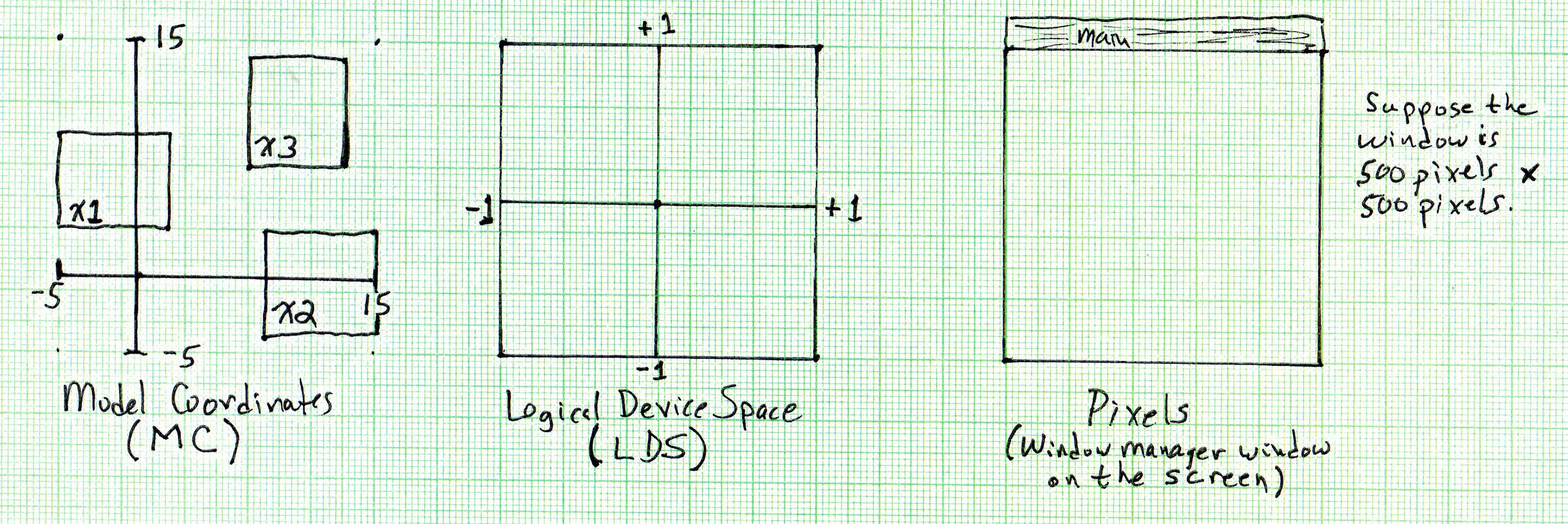
When the Controller's run method is called, it calls the render method of each of its stored models. The render method of each ModelView instance (i.e., x1, x2, and x3) then calls the common class method compute2DScaleTrans and uses the resulting x and y scale and translation to "draw" the scene into LDS. Note in particular that all three ModelView instances will be given the same x and y scale and translation (as they must).
Exercise: Verify that (sx, tx) = (1/10, -1/2) and (sy, ty) = (1/9, -5/9).
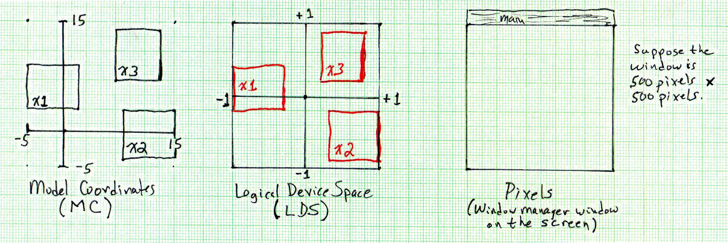
The way in which the ModelView instances "draw" the scene into LDS begins by passing (sx, tx) and (sy, ty) into the vertex shader using "uniform vec4 scaleTrans;". Each vertex shader execution uses scaleTrans to compute the LDS vertex coordinates for its vertex, storing it in the gl_Position variable. The result is:
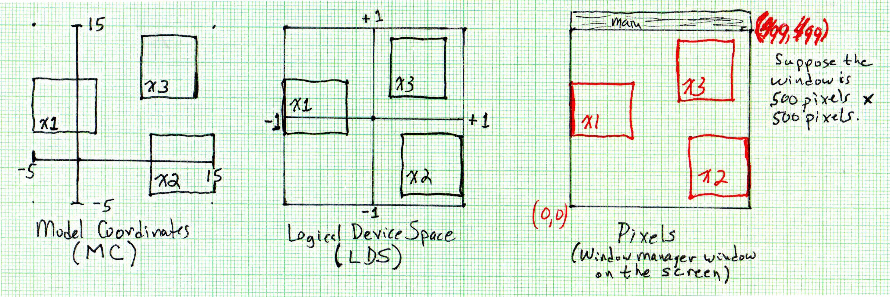
After the vertex shader executes, the OpenGL pipeline continues to process your primitives, including mapping the LDS coordinates to pixel coordinates using the size of the current window manager window as specified to glViewport. In this example, we are assuming this viewport size is 500 x 500 pixels:
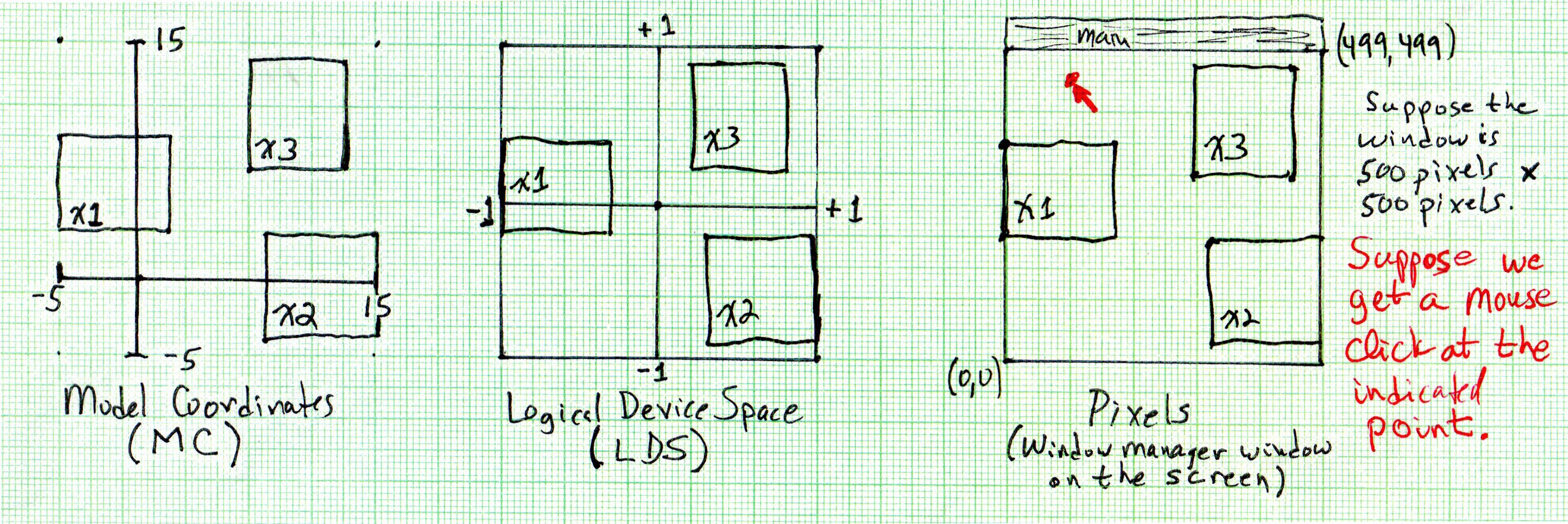
Suppose we get a mouse click at the indicated position. The window manager detects the click and knows the pixel coordinates, but we typically need to know the corresponding MC position. In terms of our framework, the Controller knows about pixels and LDS, hence it can convert pixel coordinates to LDS. But it does not know how to map LDS to MC because it does not control that mapping. Meanwhile, the ModelView knows about LDS and MC since it is in charge of converting from MC to LDS. Hence the process of mapping the pixel location of the mouse click to MC must be done in two steps:
The first issue in this step is that the GLFW window manager (as most window managers) assumes y=0 is at the top of the screen. As can be seen in this case, the point is 20% of the way from the left of the window to the right, and it is 10% of the way from the top to the bottom. Therefore the mouse click (x, y) location will be reported to the Controller as (100, 50). The Controller accounts for the y=0 difference and then maps this to the LDS point (-0.6, 0.8). (Exercise: Verify this.)
The ModelView is given LDS point (-0.6, 0.8). It knows that it used viewing limits: -5 ≤ x ≤ 15 and -4 ≤ y ≤ 14 when computing the x and y scale and translation terms, hence it determines that the MC (x, y) coordinates are (-1, 12.2). (Exercise: Verify this.)