

World and Eye Coordinate Systems
Generating views
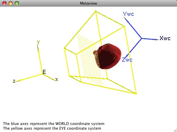
Defining a finite field of view via a frustum gets us part of the way from eye coordinates to pixels. The next piece of the puzzle involves defining a projection plane (of infinite extent) perpendicular to the eye coordinate z-axis onto which the 3D geometry is projected. The portion of this plane inside the view frustum is mapped directly to a rectangular area on the screen (the "viewport"). In the figure, a grid is drawn on this finite bounded portion of the projection plane in order to emphasize the relationship between pixels (symbolized by the small grid squares) and points in the eye coordinate space. In principal, this projection plane can be anywhere inside the frustum. However, some APIs provide direct interfaces only for special cases. For example, OpenGL's standard API always places the projection plane on the near clipping plane. For more general placements, the OpenGL programmer can fairly easily generate a custom transformation to obtain a view with the projection plane somewhere between the near and far planes.
Once the graphics programmer has specified the eye and center points along with the up direction vector, the graphics system can automatically generate a transformation matrix that will map world coordinates to eye coordinates. We will not study here the mathematical derivations. The interested reader can find details in a variety of other sources. For example, items 1, 5, and 9 in the References section elaborate on the derivation and use of this transformation.
The example we have been using here doesn't make a compelling argument for the value of the eye coordinate system or for the automatic transformation from world to eye coordinates. After all, the eye coordinate system is simply translated away from the world system along the z-axis.
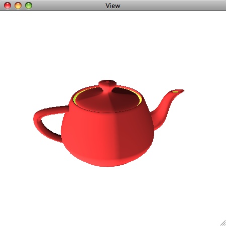
By contrast, consider the teapot in the Metaview window here. In this example, the geometry on which we wish to focus our attention (i.e., the teapot) is far away from the world coordinate origin. Moreover, we do not want a simple view parallel to a world coordinate axis. As a result, the eye and world coordinate systems have a more complex relationship to one another here. Nevertheless, once the geometry has been transformed into the eye coordinate system, it is no harder for the graphics engine to generate the desired view (as shown in the corresponding "View" window below) than it was for our initial simple cube.
Finally, let us consider general strategies for specifying the required eye, center, and up viewing parameters for a given geometric model to be displayed. As you might have guessed, there is no one "best" way to determine reasonable values. The ideal strategy depends very much on what you are trying to accomplish, what other interactive controls you are using, and – in some cases – what your conceptualization of the scene and your interactions with it are. Here we mention two simple techniques that prove to be a good place to start until you become proficient in 3D viewing. Both assume you know or can easily compute the approximate centroid, C, of your geometric model and a radius, r, such that (C, r) define a sphere that fairly tightly encloses your model. To simplify things, we assume we know what the desired up direction vector is. This is usually the case; many applications simply employ either (0,1,0) or (0,0,1), for example. With these assumptions, our challenge is to determine the eye point and the center of attention.
- If our geometric model is an object like a car, a tree, or a sculpture that we simply want to study from different exterior vantage points, then we use C as the center of attention and define the eye point something like E = C + f*r*v, where f is a factor that describes how far from our enclosing sphere we want to be. If f=1, for example, our eye is very close to the object. If f=10, we are far away. The vector v is some desired direction from which we want to view the object. For starters, v may be something very simple like (0,0,1). In our cube example, we used f=1.2 and v=(0,0,1). To generate views of the object that simulate walking around it, simply vary v in a systematic fashion. For example, imagine generating a series of points around a unit circle determined by C and the up direction vector. For each point P around this circle, create v = P-C. (Equivalently, slice the sphere (C, f*r) with a plane – for example, the plane determined by C and the up direction – and generate eye points, E, directly by generating points around the circumference of the circle.)
- If instead our geometric model is an environment in which we want to place ourself (e.g., the model is a room and I want to see various views of the room as I turn around), then we fix the eye point as E=C (or some other appropriate point inside the sphere determined by (C, r)) and generate a series of centers of attention for several views in the same way we generated eye points in #1 above.
Finally, it is important to understand the relationship between the eye coordinate system and the view frustum. Specifically, the latter is defined in terms of the former in most graphics APIs. That is, when you specify the limits of the view frustum, you generally specify them in terms of min and max eye coordinate system limits. Thus as you move the eye, alter the up vector, etc., the frustum changes as well. You will see this firsthand in some of the exercises on the next page.
An implication of the previous is that if you define the eye coordinate system as implied in item #1 above, you can always specify the view frustum so that it is symmetric about the z-axis of the eye coordinate system. It can be specified as something very similar to (xmin,xmax,ymin,ymax,near,far) = (-r, r, -r, r, (f-1)*r, (f+1)*r), where f and r are as described in #1 above.
On the final page of this section, you will be asked to run the program that generated the images on these pages and try out some of the general viewing strategies presented.