The color we generate for a visible surface point in our scene is a function of the material properties of the object (loosely, "its color") and the position and properties of the lights in our scene. For now, we are going to make several simplifying assumptions:
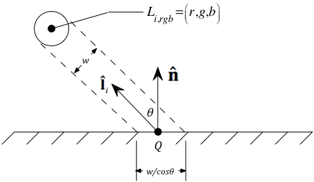
The geometry we will assume in our 101 lighting model is shown in the figure on the right. Let's consider how the actual values for these geometric quantities are determined.
The scene designer models the vertices and associated normal vectors, generally placing them in VBOs as you
have already seen. The vertex shader transforms them from MC to EC, and then passes them on to the fragment
shader where the lighting model is actually evaluated. The fragment shader runs once per pixel in the primitive,
and the points and normals are linearly interpolated across the interior of the primitive.
They come into the fragment shader shell we have seen as
ecPosition ("Q") and ecUnitNormal ("![]() "), respectively.
"), respectively.
The information to determine this is also created by the scene designer and passed to the fragment shader using
uniform variables. However
for now while we are learning "101 level" lighting, we are simply going to assume that this vector (in eye
coordinates!) is always  = (0, 0, 1).
That is, the 101 model essentially simulates a flashlight that the viewer is holding and shining on the scene.
= (0, 0, 1).
That is, the 101 model essentially simulates a flashlight that the viewer is holding and shining on the scene.
In addition to visualizing model geometry, the figure on the right also shows why the intensity (or brightness) of the color generated for Q falls off as the angle of incidence of the light grows. Specifically, since the beam of light is spread out over an area proportional to cos(θ), the intensity at any given point (e.g., Q) drops off with this value.
Recall also that each primitive has non-geometric attributes that describe its reflectance properties. For now, we are interested in just two of these: an ambient reflectance, ka=(kar, kag, kab), and a diffuse reflectance, kd=(kdr, kdg, kdb). These values represent the fraction of incident light of the indicated wavelengths that gets reflected.
Using simplifying assumption #1 above, the light source strength, Li, rgb = (1, 1, 1) and
= (0, 0, 1).
The background light mentioned in simplifying assumption #3 above is denoted as
La=(Lar, Lag, Lab).
So combining all three simplifying assumptions means we can write the equation for
the color to be displayed for our point, Q, as:
Each of the bold I, k, and L symbols is an (r,g,b) triple, hence this expression really represents three equations, one for each of r, g, and b. The multiplication and addition operations are done component-wise. (Multiplication, for example, is not a dot product here.) So, for example:
In GLSL, this is exactly what happens when you multiply two vec3 instances (and analogously add or subtract two vec3 instances).
So everything looks simple. Right?
Actually, except for one minor issue, it is.
What happens if the dot product in our lighting model equation is negative? Physically, this means the light is on one side of the surface, but we are viewing it from the other side. (Make sure you understand this!) Hence the light should not contribute to I at all, and I should simply be ka*La in this case. Stated another way, I may be looking at either side of the surface, but since the light is only on one side, it will look brighter if I look at it from that side than it will if I look at it from the other side.
But here is the problem from the geometry modeling perspective. The argument in the previous paragraph assumes that the normal vector is pointing away from the side of the triangle on which the viewer lies. Unfortunately, we cannot be assured of this. The normal vector is really only useful for specifying the orientation of a triangle. The scene modeler must specify this orientation independent of the particulars of the lighting environment. Therefore, it must not matter whether the modeler specifies, for example, n=(-1, 0, 1) or n=(1, 0, -1) – both specify the same triangle orientation. It follows, therefore, that simply getting a negative dot product by itself is not sufficient to conclude that the light source should be ignored at the current point. The correct decision can only be made point by point as the lighting model is being evaluated in the fragment shader. But how? Before trying to compute the lighting model at a point, we must first decide for that point whether we need to "correct" (i.e., negate) the normal vector supplied by the scene designer. Then – and only then – can we make a reliable decision as to whether a light source is to be used at a given point on the surface.
Read on for details.
To be useful in our lighting model equation, the unit normal vector to the surface must point towards the side of the
surface on which the viewer lies. This can only be checked (and, if necessary, corrected) in the fragment shader.
Here is how to do it. I first
get a unit vector towards the viewer, ![]() , and then look at the expression:
, and then look at the expression:
![]() ·
·![]() .
If it is negative, then we must "correct"
.
If it is negative, then we must "correct"
![]() by using –
by using –![]() instead. (Why?)
instead. (Why?)
Determination of the vector ![]() towards the viewer depends on
the current projection type. The fragment shader
needs to examine the ec_lds matrix and determine this vector. As we will see later when studying how these matrices are
determined:
towards the viewer depends on
the current projection type. The fragment shader
needs to examine the ec_lds matrix and determine this vector. As we will see later when studying how these matrices are
determined:
It turns out that we need not distinguish between the orthogonal and oblique
cases in the code. Again, as we will see later when studying how these matrices are
determined (see projection matrix
summary if you want a "sneak preview"), it will be
clear that, regardless of whether the projection is orthogonal or oblique,
![]() = normalize(Dx, Dy, 1), where
Dx = –ec_lds[0][2]/ec_lds[0][0], and Dy = –ec_lds[1][2]/ec_lds[1][1].
= normalize(Dx, Dy, 1), where
Dx = –ec_lds[0][2]/ec_lds[0][0], and Dy = –ec_lds[1][2]/ec_lds[1][1].
IMPORTANT IMPLEMENTATION NOTES:
Dx = –ec_lds[2][0]/ec_lds[0][0]