EECS 700:
M-ary Pulse
Amplitude Modulation (MPAM)
Objective
The goal of this exercise is to correctly demodulate the noisy
received signal in Rx8PAM.mat. The
major new "step" in this exercise is the need for proper DECISION logic
(not just a simple SIGN operation).
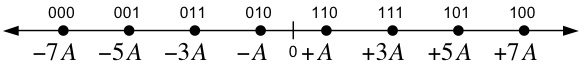
Signal Constellation
The transmitted data points are taken from the signal space
constellation below. The 8 points are equally spaced on a line
with a spacing of 2A.
Each
transmitted signal carries three
information bits, as shown below.
After being corrupted by noise, the received signal is demodulated by
the system below, which detects the transmitted signal space points and
outputs the estimated values of the transmitted bits.
Design Exercise
Part I: Generic MPAM Transmitter
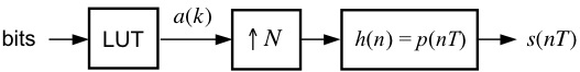
Using blocks from the SIMULINK Block Library, the Signal Processing
Blockset, and the Communications Blockset, design a MPAM modulator,
patterned after the one shown above, to meet the following
specifications:
Number
of samples per symbol: 16
Pulse shape:
HS
Average
energy:
84
As you can see, the above modulator is identical to the Binary PAM Modulator. The only
difference between
modulators for M=2 and M-arbitrary is the contents of the respective
look-up
tables (in fact, the binary PAM case was so simple, we did not need a
look-up table).
Part II: Generic MPAM Detector
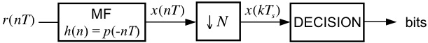
Using blocks from the
SIMULINK Block Library, the Signal Processing
Blockset, and the Communications Blockset, design a MPAM detector,
patterned after the one shown above, that is compatible with the
modulator from Part I. In your implementation, you might find it
eaiser to output the signal space projections, x(kTs), to the MATLAB
workspace
and implement the decision logic in a post-processing fashion using a MATLAB script or MATLAB function. Adding the
functionality of the DECISION block is the only thing that is really
"new" in this lab exercise.
[ Sanity Check ]
You can test your designs from Parts I and II by connecting the
output of your modulator to the input of your detector. The data
source (Signal from Workspace block) emits symbol indexes, which are
integers in the range 0 to 7 (each of these integers has a 3-bit
representation). Set this block to output the
four-symbol sequence [0 2 5 7]'. The look-up table
converts these indexes to the constellation points. In your
project
window, go to the menu Simulation --> Configuration Parameters and
set the parameters to:
Start
Time: 0.0
Stop Time:
(4+1)*16
Solver options: Type: Fixed-step, Solver: discrete
(no continuous states)
Fixed step size: 1
Note: The 4 corresponds to
the number of transmitted symbols, the 1
corresponds to the delay of the downsample operation in the detector,
and the 16 is the number of samples per symbol.
Remember, it
is very important that your Downsample block is sampling at the correct
"phase". This may require some adjustment/experimentation on
your part. If you plot an eye diagram, this will tell you if your
implementation is correct enough, because you will be able to see the
correct sampling instant. After that, it is just a matter of
adjusting the sampling phase so that you sample these points. You want
to sample the matched filter outputs when the
signal passes exactly through the constellation points. When you have
successfully debugged your
system, you are ready for the final part of the exercise.
Part III: Detecting an
Unknown Data Set
Here are the steps for the final
part of the exercise:
- Connect the input of your detector to a From File
block and set the filename to Rx8PAM.mat (If you have problems with that file, here is a ZIP version).
- Set the simulation
parameters to:
Start
Time: 0.0
Stop Time:
(42+1)*16
Solver options: Type: Fixed-step, Solver: discrete
(no continuous states)
Fixed step size: 1
- Run the Simulation.
- The last 42 values of
the sampled matched filter outputs represent 18 ASCII characters.
Determine the message using your own conversion script or an ASCII
table, such as the one found here.
- Submit your answer AND
your detector model file (.mdl SIMULINK file) to the class TA via the
Digital Drop Box in Blackboard (you may submit via e-mail only if you
have
problems with Blackboard). You should organize your files into a
folder, and then ZIP the folder and submit the ZIP file. The
naming
convention for the ZIP file is "Lab#_YourLastName.zip."
- Plot the eye diagram
and signal space projections. You may submit these
electronically, or turn them in at the beginning of the next class
period after the due date.
Back to the Lab
Exercises Page