The glDrawArrays call you saw in "Hello, OpenGL" is one of the most common ways of rendering a primitive in OpenGL:
The "Arrays" part of the name refers to the fact that the per-vertex attribute data are assumed to be in parallel arrays in VBOs. Another very common such primitive is:
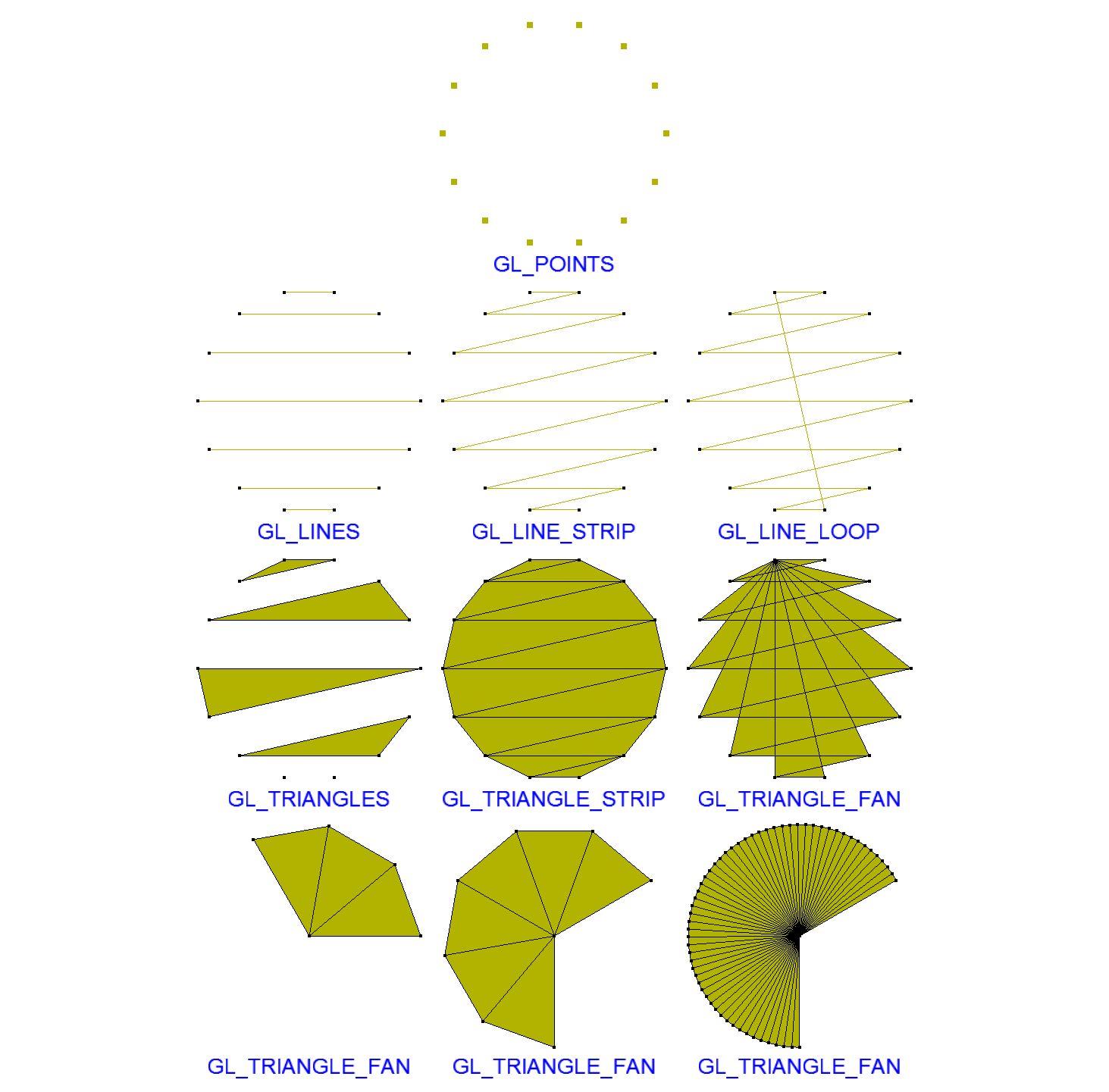
We will study glDrawElements more closely later, but for now note that the first parameter to both is an OpenGL enumerated type ("mode") that describes how the vertices retrieved from a VBO are to be reassembled during the "Primitive Assembly" stage of the pipeline we studied. Click here (or on the image on the right) for an illustrated explanation of supported modes along with a glimpse into the use of glPolygonMode for controlling how the primitive is actually rendered.
Each draw mode assumes a specific order in which vertex coordinates (and associated attributes) are placed in VBOs. You must pay close attention to this. Notice that the description of the "Point Association Modes" page linked from the image on the right states "The points are stored in the coordinate buffer in a left-to-right, top-to-bottom order." Had they been stored differently, the resulting geometry would have looked radically different.


Let's explore this a little further with the example on the left. To create a shape such as that shown by the solid lines, we create and store vertices in a VBO in the exact order indicated. For example, we create vec2 pts[] = { {x0, y0}, {x1, y1}, …, {x9, y9} } and send the data to a VBO on the GPU via glBufferData. Then if we issue a glDrawArrays call using GL_TRIANGLE_STRIP while that VBO is bound, we obtain the indicated shape. The dashed lines simply indicate the triangles produced by OpenGL in response to the glDrawArrays call; the shape itself would typically be drawn as a solid shape as shown below on the right.
Triangle strips are very useful when we wish to render a shape that can be defined by two bounding "paths" like this, each consisting of the same number of points. We place the points in a VBO by "bouncing back and forth" between successive points on the two "paths". The points may all lie in a common plane as indicated here. Alternatively, they may represent vertices of a cube; they may be parallel paths along some curved surface such as a cylinder or a Bezier surface; etc.

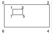
Note also that this same approach can be used to render, say, a rectangle with an inner rectangular hole like that on the left by "bouncing back and forth" between corresponding points on the outer and inner rectangles. A VBO with 10 points will be required – the last two will be a copy of the first two. Labeling the vertices as indicated on the right, we would create our VBO using a C++ array:
vec2 rectWithHolePts[] = { {x0, y0}, {x1, y1}, {x2, y2}, {x3, y3}, {x4, y4}, {x5, y5}, {x6, y6}, {x7, y7},
                           {x0, y0}, {x1, y1} };
These same draw modes are used in several other OpenGL primitives. Another very useful such primitive we will soon see is glDrawElements. That primitive allows you to randomly access the point attributes in a VBO rather than being forced to process only contiguous subsets of them.