Comparing Planar Geometric Projections
Preliminaries
A 3D to 2D projection can be characterized by specifying (i) a "family of projection lines",
and (ii) a projection plane. Each line in the family must intersect the projection plane
in exactly one point.
For any given 3D point, Q (with the possible exception of one),
there must be exactly one projection line in the family passing through Q.
The 2D projection of the 3D point Q is the point Q′ on the projection plane
at which the corresponding line intersects it.
Even though the immediate goal is to determine how our 3D geometry will project and appear on
our 2D display, we will want the matrix representation to encode a
"3D to 3D projection". Specifically, we will want to preserve a measure of depth so
that subsequent
graphics pipeline processes such as visible surface determination will be able to function
correctly.
The Three Most Common Planar Geometric Projections
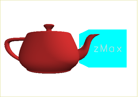
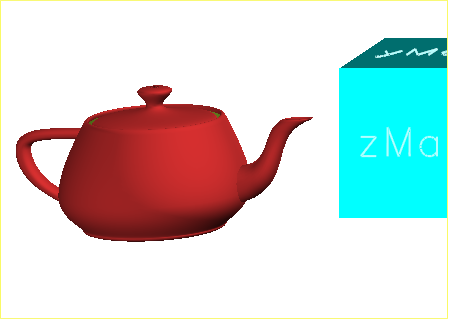
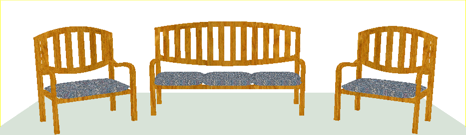
Each of the images in the first column below was generated using
the same model coordinate to eye coordinate transformation (i.e., the same (eye, center, up)
specification),
but with the different projections
illustrated in the second column.
⇒ Note, too, that the Model Coordinate axes are not shown here. That coordinate system is no longer
relevant in the context of projections!
Relevant Class Method Declarations in Matrix4x4.h
static Matrix4x4 perspective(double ecZpp, double ecXmin, double ecXmax, double ecYmin, double ecYmax, double ecZmin, double ecZmax);

static Matrix4x4 orthogonal (              double ecXmin, double ecXmax, double ecYmin, double ecYmax, double ecZmin, double ecZmax);

static Matrix4x4 oblique    (double ecZpp, double ecXmin, double ecXmax, double ecYmin, double ecYmax, double ecZmin, double ecZmax, const AffVector& ecProjDir);
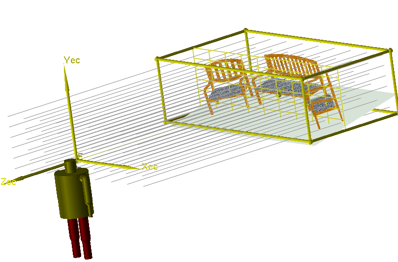
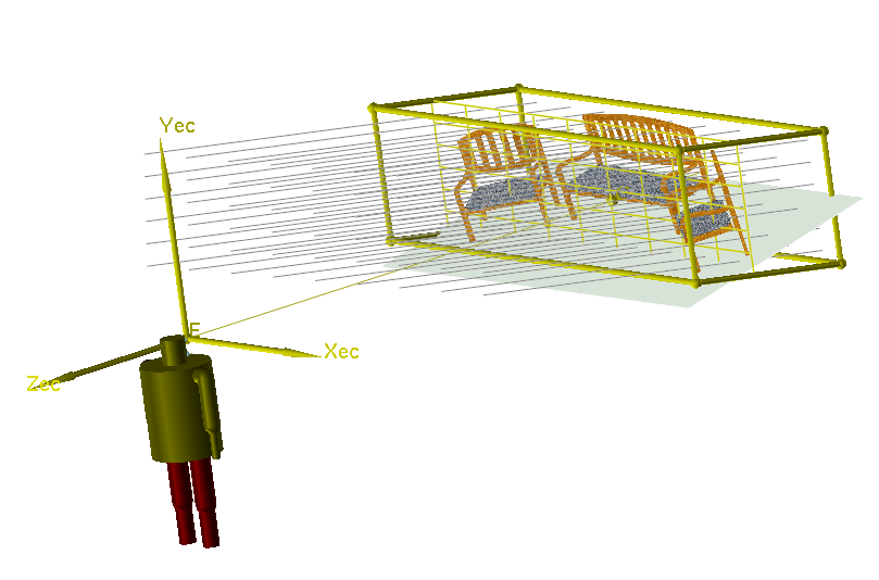
In the drawings below, the yellow view volume depicts the region of space which will be visible; its
shape and extent are
defined by the projection type along with the specific
(ecXmin, ecXmax, ecYmin, ecYmax, ecZmin, ecZmax) values. The xy-portion of this view
volume is defined to be on the projection plane, depicted in the drawings as the grid
perpendicular to the
line of sight (and hence parallel to the ecZmin and ecZmax planes).
A Historical Reference
My favorite classical reference for understanding planar geometric projections, including history, classification,
current usage, and mathematics is:
- Planar Geometric Projections and Viewing Transformations, Ingrid Carlbom and Joseph Paciorek, ACM
Computing Surveys, Vol. 10, No. 4, December 1978, pages 465-502.
Examples
Example 1: Teapot and XYZ Cube
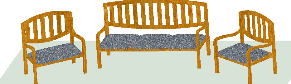
Example 2: Chair Garden