3D Dynamic Modeling
Transformations are commonly used to animate scenes, particularly those in which some object is
to be articulated (e.g., a robot walking and moving its arms) and/or moved independently
from other objects during the course of an animation.
We have already seen how the Mdynamic_view
matrix is used to support dynamic view manipulations that affect the scene as a whole. Here we will introduce another
matrix – Mdynamic_model – that will change during the course of a display update.
Examples of how this facility can be used include:
- Model construction via instantiation of shapes
- A model of a wheel placed four times on a car using four
different affine transformations
- A street scene constructed by placing multiple cars on a street
- Animation of objects in a scene
(Mdynamic_model)
- Two cars pass each other while traveling in opposite
directions on a street with houses and trees.
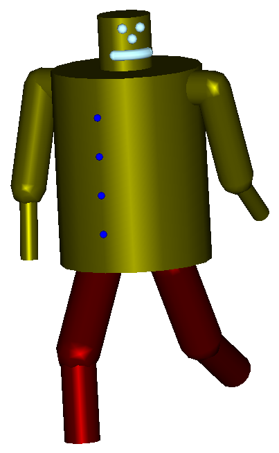
- Articulating the joints of a human or robot to simulate
walking around while using its arms and hands.
In terms of the matrices we have seen so far, the dynamic operations indicated above will be encoded
in affine transformation matrices and used as follows:
MECu = lookAt(eye, center, up)
mc_ec = Mdynamic_view * MECu * Mdynamic_model
Note that the matrices for dynamic viewing and dynamic modeling are applied on opposite sides
of the MECu matrix. As we proceed, we will come to understand why that is.
Be very sure you understand the reasons by the time we are done.
Comments
- The mathematics and mechanics of generating the transformation matrices themselves are identical
to what we studied for dynamic view manipulations. From a user interface perspective, dynamic view manipulations are
typically driven by direct user interaction (e.g., mouse-based operations). While dynamic modeling may be controlled the
same way, it is also often driven using timer-based logic.
- The modeling technique #1 above typically involves initial
construction of models from a collection of low-level components defined in "local" model
coordinate (MC) systems which are then assembled in a hierarchical fashion into
successively "higher level" MC systems until a complete scene is created in the "topmost" MC.
For example, a model of a
car wheel will be defined in its local MC and placed four times on a car in its local MC.
The car may be placed several times while
creating a model of a parking lot full of cars in its local MC, and finally
the parking lot model may be placed several
times along a busy commercial street inside the topmost MC system. It is then with respect to
this topmost MC system that we define an eye point, center of attention, and up vector while
defining a view of the scene.
Of course, just because the same model geometry is used to create many copies of scene components,
their display attributes need not all be the same. Since these are generally defined via PPUs, we can
easily adjust those values for each instance so that, for example, each car can be a different
color.
- For our purposes, the primary difference between modeling techniques #1 and #2
is that the matrices will be allowed to change dynamically in #2 as we simulate the advance of time.
We will study both the mathematical implementations and the control mechanisms for these two
techniques. We will begin by studying structured models using the technique associated with
"Mdynamic_model" above.
Using Mdynamic_model to Implement Hierarchy in Construction and Articulation of Models
Tools & Implementation Notes
The cryph::Matrix4x4 class includes several methods for constructing the transformation matrices.
You should review the cryph::matrix4x4 class documentation
(cryph
utilities) for details.